|
|
|
News
All Interfaces of PC 101
| Author:admin Date:2012/6/25 0:55:28 |
PC Interfaces 101
Males And Females Must Fit Together
 Every computer system, whether a desktop PC or a notebook, includes a bunch of connectors, both inside and out. Can you recognize each and every one of them? Relevant handbooks, when they're even available, are often poorly worded or insufficiently illustrated. This causes readers to lose their orientation and leads to confusion and frustration.
This comprehensive advisor is intended to function as a reference, aimed at helping newbies and experienced users alike. With numerous pictures and short explanations, we'll tell you all about the slots, ports, and connectors you'll find on your PC, and what kinds of devices typically attach (or plug in) to them. We're especially interested in helping those users out who may not know all the many acronyms associated with computer peripherals, but who seek immediate solutions to their connectivity and assembly problems.
There's one consolation when it comes to connectors though - nearly every one is designed to make it difficult (if not impossible) to reverse polarity when hooking things up. With few exceptions, it is also not possible to plug incompatible devices and interfaces into each other; in the few cases where such possibilities exist, we'll be sure to warn you about them explicitly. But the good news is that damage or destruction caused by reversed connectors is pretty much a thing of the past.
Our adviser is also divided into the following sections:
External: connectors for external peripherals
Internal: connections inside a PC system
Every computer system, whether a desktop PC or a notebook, includes a bunch of connectors, both inside and out. Can you recognize each and every one of them? Relevant handbooks, when they're even available, are often poorly worded or insufficiently illustrated. This causes readers to lose their orientation and leads to confusion and frustration.
This comprehensive advisor is intended to function as a reference, aimed at helping newbies and experienced users alike. With numerous pictures and short explanations, we'll tell you all about the slots, ports, and connectors you'll find on your PC, and what kinds of devices typically attach (or plug in) to them. We're especially interested in helping those users out who may not know all the many acronyms associated with computer peripherals, but who seek immediate solutions to their connectivity and assembly problems.
There's one consolation when it comes to connectors though - nearly every one is designed to make it difficult (if not impossible) to reverse polarity when hooking things up. With few exceptions, it is also not possible to plug incompatible devices and interfaces into each other; in the few cases where such possibilities exist, we'll be sure to warn you about them explicitly. But the good news is that damage or destruction caused by reversed connectors is pretty much a thing of the past.
Our adviser is also divided into the following sections:
External: connectors for external peripherals
Internal: connections inside a PC system
Connector Table
| External - connectors for External Peripherals |
| Plug |
Socket |
Name |
 |
 |
USB
|
 |
 |
IEEE1394 / Firewire / i.Link
|
 |
 |
Cinch / RCA (Composite, Audio, HDTV Components)
|
 |
 |
PS2
|
 |
 |
VGA
|
 |
 |
DVI
|
 |
 |
RJ45 (LAN /ISDN)
|
 |
 |
RJ11 (Modem / Telephony)
|
 |
 |
S-Video (Hosiden)
|
 |
 |
SCART (Peritel / Euroconnector)
|
 |
 |
HDMI
|
| Internal - Connections Inside a PC System |
| Plug |
Socket |
Name |
 |
 |
SATA (Serial ATA)
|
 |
 |
PATA (Parallel ATA / UltraDMA/133 / IDE)
|
 |
 |
AGP (Graphics Cards)
|
 |
 |
PCIe (PCI Express)
|
 |
 |
PCI
|
 |
 |
Power Supply connectors
|
External: connectors For External Peripherals
USB
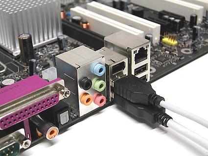
Universal Serial Bus (USB) connectors are designed to connect computers up to external peripheral devices such as a mouse, keyboard, portable hard disk, digital camera, VoIP telephone (Skype), or printer . Theoretically, up to 127 devices can be attached to a single USB host controller. Data transfer rates for this interface tops out at 12 Mbps for USB 1.1 and at 480 Mbps for USB 2.0. The connectors themselves don't differ for USB 1.1 and 2.0; differences in transfer rates are a function of the USB host controller in the computer and the USB devices themselves. USB offers integrated power delivery through the interconnecting cable, so that USB devices such as external hard disks can operate without their own independent power supplies (provided that they don't need more current than the USB interface can deliver: a maximum of 500 mA at 5 V).
There are three types of USB connectors:
- Type A connector: typically found on the PC
- Type B connector: typically found on the USB device itself (if it has a detachable cable)
- Mini-USB connector: typically found on digital still and video (camcorders) cameras, measurement instruments, and external hard drives
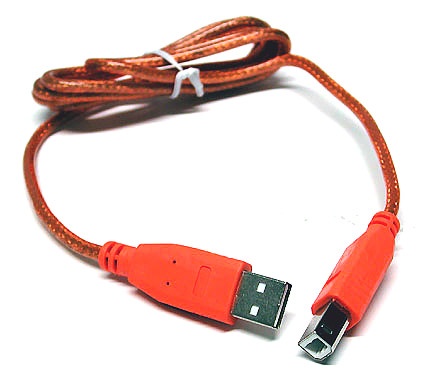
USB Type a (left for computer link) and USB Type B (right for devices)
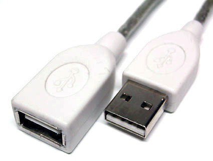
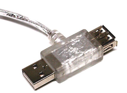
USB Extension Cables (should never be more than 16.4 ft/5 m)
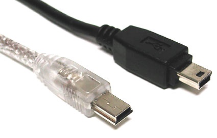
USB Mini connectors are typical on digital cameras, external hard disks, or mea surement instruments
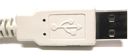
The USB logo is always worked into the connector itself
Split cable: 5v and 500 mA are available from each USB port; those devices that need more power (such as a mobile hard disk) can use this cable to draw additional power from a 2nd USB port (500 + 500 = 1000 mA)
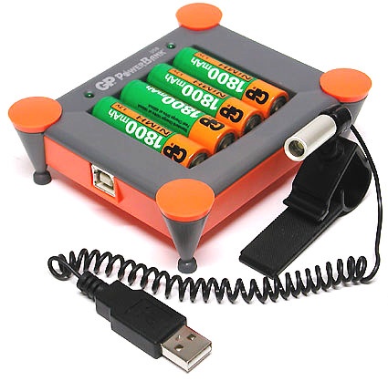
Curiousity: In this case USB serves only to provide power for a battery charger, making the otherwise obligatory brick unecessary.
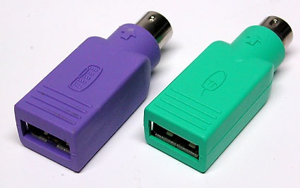
PS2 USB Adapter
IEEE-1394 / Firewire / i.Link
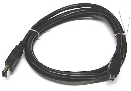
Firewire cable with 6-pin connector on one side, and a 4-pin connector on the other
IEEE-1394 is the formal name for the serial interface commonly used for connecting digital video cameras (camcorders), external drives and various networked devices; it is also called Firewire (Apple's name) and i.Link (from Sony). At present, the 400 Mbps IEEE-1394 standard is being superseded by 800 Mbps IEEE-1394b (also known as Firewire-800). Ordinary Firewire devices connect through a 6-lead assembly that provides power through the link; the 4-lead version lacks power capability. Firewire-800 devices, on the other hand, use 9-lead cables and connectors.
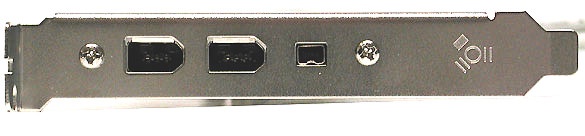
This Firewire card offers two large 6-pin ports with one smaller 4-pin variant
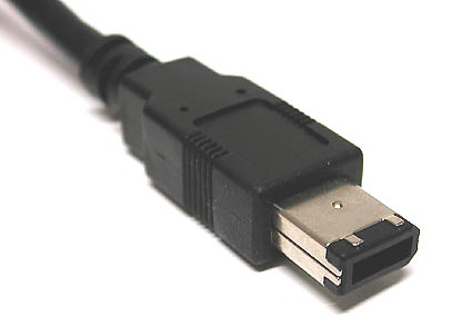
Detail: the 6-pin connector with integrated power leads
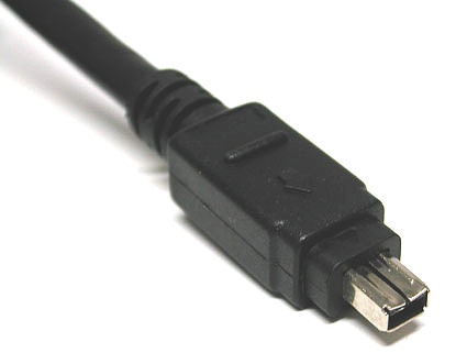
Detail: the 4-pin connector without power leads, typical for digital video cameras (camcorders) and notebooks
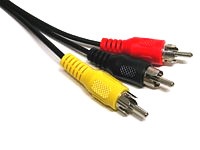
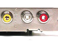
Cinch RCA (Composite, Audio, HDTV Components)
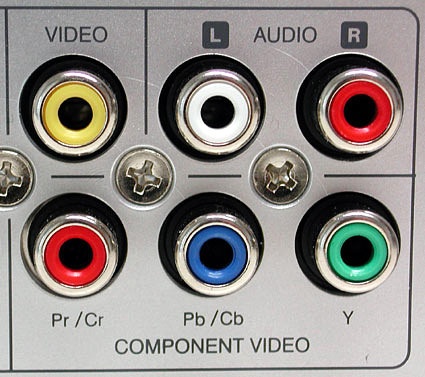
Color coding example from a typical set-top box: yellow for composite video (FBAS), a pair of white and red jacks for analog stereo, and a trio of jacks in red/blue/green for HDTV components
These are used with coaxial cables for many types of electronic signals. The connectors are easily differentiated through the use of color, as follows:
| Color |
Use |
Signal Type |
| white or black |
Audio left channel |
analog |
| red |
Audio right channel, also see HDTV |
analog |
| yellow |
Video Composite |
analog |
| green |
HDTV Components Y Luminance with sync-on-green |
analog |
| blue |
HDTV Components Cb/Pb Chroma |
analog |
| red |
HDTV Components Cr/Pr Chroma |
analog |
| orange/yellow |
Audio SPDIF |
digital |
Warning: It's possible to mix up audio SPDIF with composite video connectors, so please always consult your handbook for their proper connection and use. Use of color for SPDIF isn't always consistent, either. Furthermore, it's possible to switch the red HDTV connector with the right audio channel. HDTV components always appear in groups of three on device panels, so be sure to match them up with three-element cables and connectors.
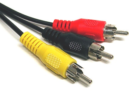
RCA connectors in various colors for different types of signals
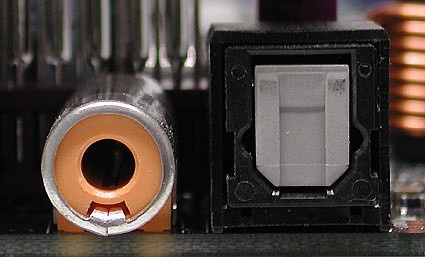
Two types of SPDIF (Digital audito): an RCA/coax connector on the left, and a TOSLINK (optical fiber) on the rigth
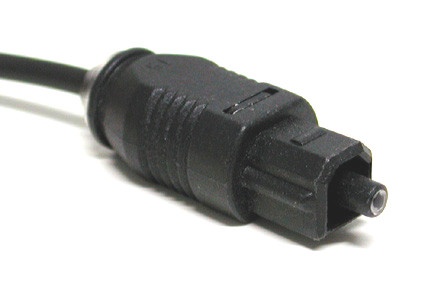
TOSKLINK connector for optical delivery using fiber optic cable for digital SPDIF signals
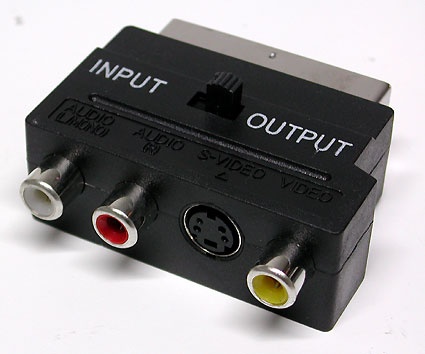
An adapter from SCART to RCA connectors (Composite-Video, 2x audio, and S-Video)
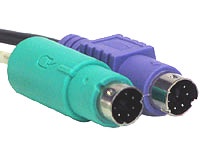
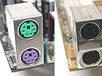
PS/2
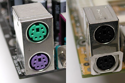
Two PS/2 ports: one color-coded, the other color neutral
Named for the old IBM PS/2, these connectors have been widely used as the standard interfaces for keyboards and mice, but are slowly giving way to USB. The following color coding schemes for connectors are widely used:
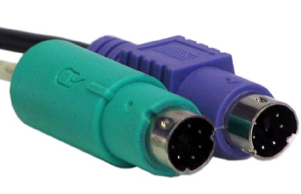
- Violet: keyboard*
- Green: mouse
It's also quite common to see such connectors in a neutral gray color on both mouse and keyboard. Switching the mouse and keyboard connections on the motherboard port block is possible, but is harmless. If you do this you will quickly know it, because if these connections are switched neither mouse nor keyboard will work. Many PCs won't even boot if keyboard and mouse are inadvertently switched. The fix is quick and easy: switch the two connectors around the right way, and everything should work!
USB PS/2 Adapter
VGA Monitor Interface
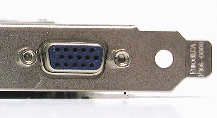
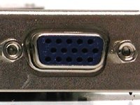
VGA monitor port on a graphics card
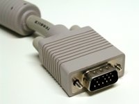
Standard analog interfaces to connect a monitor to a PC using a 15-pin Mini-D-Sub connector, aka HD15. With the right adapter, you can also connect an analog monitor to a DVI-I (DVI-integrated) interface as well. The VGA connector carries RGB signals for red, green, and blue color values, as well as horizontal (H-Sync) and vertical (V-Sync) information.
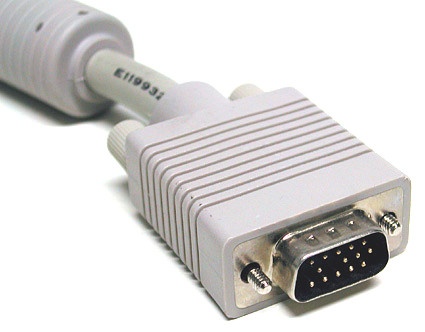
VGA connector on a monitor cable
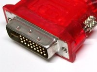
Newer graphics cards often include 2 DVI ports. But it's easy to use a DVI-VGA adapter to switch connections as needed (right in the picture).
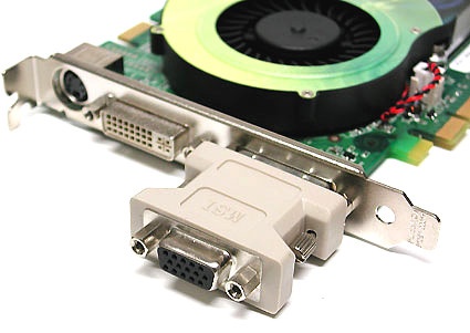
This adapter configuration outputs VGA video signals
Glossary
- VGA = Video Graphics Array
DVI Monitor Interface
DVI is a monitor interface developed primarily for digital signals, to eliminate the need to convert digital signals into loss-prone analog counterparts on the graphics card, and then to reverse this process to go back to digital in display devices. In addition, digital TDMS signals also enjoy the advantage of allowing display devices to handle image positioning and signal synchronization.
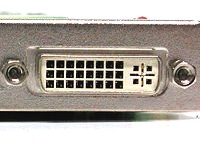
A graphics card with two DVI ports permits simultaneous use of two (digital) monitors
Because the switchover from analog to digital graphics continues to proceed slowly, developers of graphics gear typically allow the parallel use of both technologies; among other things, this permits modern graphics cards to drive two monitors.
The widely used DVI-I interface supports simultaneous analog and digital signaling.
Though still rare, you'll also occasionally encounter DVI-D , designed exclusively for digital use (without any analog capability whatsoever).
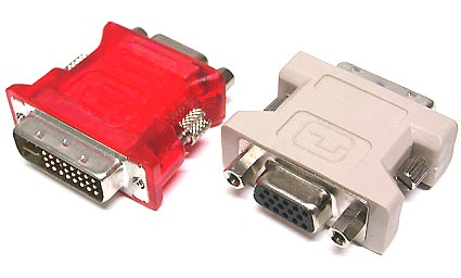
An adapter that converts from DVI-I to VGA signals is included with many graphics cards (and some monitors) to permit continued use of older monitors that offer only the older 15-pin D-Sub-VGA connectors.
Complete list of DVI Types (the most widely used is on graphics card with both analog and digital ports, or DVI-I)
Glossary
- DVI = Digital Visual Interface
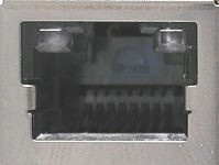
RJ45 For LAN And ISDN
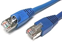
RJ45 network cables come in different lengths and colors
Interfaces for wired networks primarily use the familiar twisted pair Ethernet cables. Right now, 100 Mbps Ethernet is giving way to Gigabit Ethernet (which runs at 1 Gbps, as the name indicates). Such network cables come in two primary types:
- The classical patch cable, the most widely used form of pre-fabricated twisted pair cables
- The crossover cable, used for special connections and situations
All network connections that use a patch cable generally come together at a switch or a hub, devices that handle data management for the network. If you want to make a network connection directly (and only) between two devices such as PCs - perhaps to synchronize files between a notebook and your home PC - the crossover cable provides an interesting alternative to using a switch or hub.
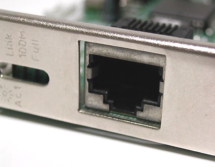
Network port on a PCI network card
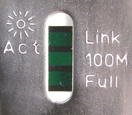
Modern products use blinking LEDs to report network activity
In Europe and North America, ISDN and network devices use the same RJ45 connector. ISDN is more widely used in Europe; in North America, broadband connections are more common but only DSL uses RJ45: cable modems typically use BNC connectors instead. The use of the same connector for ISDN and DSL means users should always pay close attention to port labels (normally they will be marked "LAN" versus "ISDN" or "DSL"). However, even if the connector gets plugged into the wrong port, you needn't fear that devices will be damaged or destroyed.
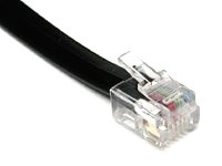
RJ11 For Modems And Telephony
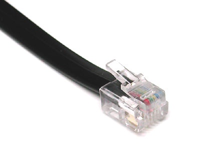
RJ11 connection cable
The RJ45 network connector and the RJ11 look superficially alike, but the RJ11 has only four leads (or contacts) whereas the RJ45 has eight. In computer systems, the RJ11 is used primarily for connecting to modems. There are many different adapters for RJ11 connectors, because telephone ports vary widely from country to country.
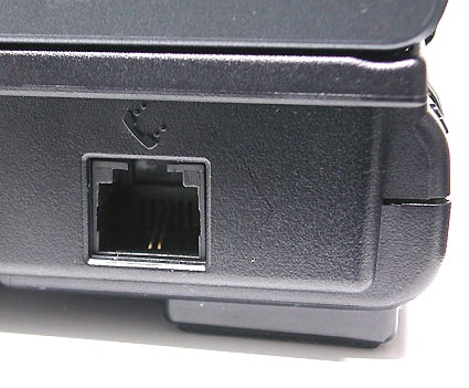
RJ11 ports on a notebook PC
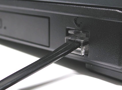
RJ11 modem connector
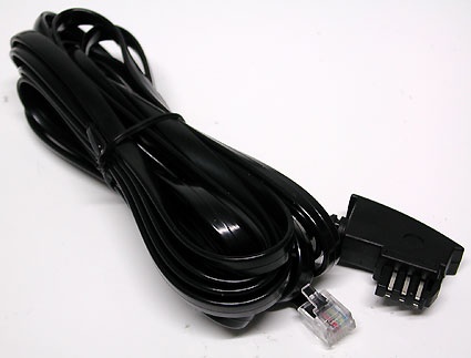
RJ11 adapters convert between regional telecomm variations, this one works for Germany. In the long term country-specific versions are on the wane.
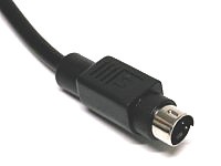
S-Video (Hosiden, Y/C)
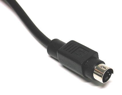
S-Video connector
Separate lines for brightness (Y, luminance with synchronization data) and color (C, chrominance) via a 4-pin Hosiden connector. By separating luminance and color signals, better image quality is delivered when compared to composite video (FBAS) connections. In the realm of analog image signals, HDTV Components represent the best connection type followed by S-Video. Only pure digital signals such as DVI (via TDMS) or HDMI (via TDMS) offer a better picture, and represent today's optimum choices.
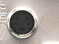
S-Video port on a graphics card
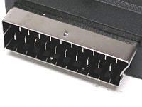
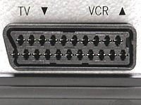
SCART
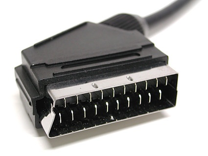
SCART is a combo-connector widely used for consumer electronics in Europe and Asia. This connector carries S-Video, RGB, and analog stereo audio signals together. The YpbPr and YcrCb color models are not supported, though normally used for analog HDTV components.
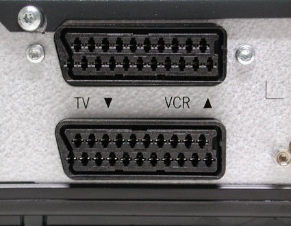
SCART ports for TV and video recorder on a set-top box
This adapter converts from SCART to S-Video and analog stereo audio (RCA plugs)
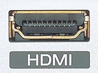
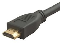
HDMI
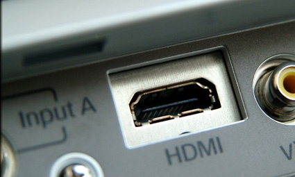
Digital multimedia interface for uncompressed HDTV signals up to 1920x1080 interlaced (aka 1080i), with integrated Digital Rights Management (DRM) copy protection mechanisms. The current technology in use today is a Type A connector with 19 pins.
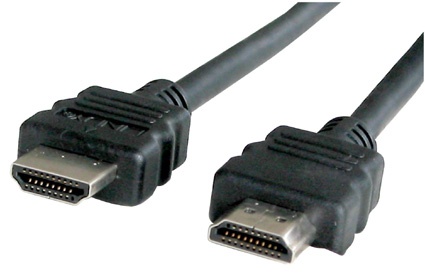
There are no consumer products available today that use the 29-pin Type B connector (which handles resolutions higher than 1080i). The video signal for HDMI uses the same digital TDMS signaling technology that DVI-D also uses. This explains why HDMI-DVI adapters are also available for high-end video gear. In addition, HDMI can also deliver up 8 audio channels using 24-bit signals and 192 kHz sample rates. Note that HDMI cables shouldn't exceed 50 feet (15 m) in length.
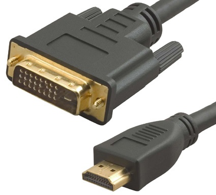
HDMI DVI adapter cable
Glossary
- HDMI = High Definition Multimedia Interface
Inside The Box: Connections Inside A PC System
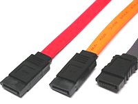
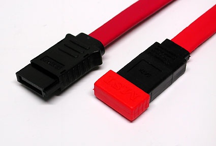
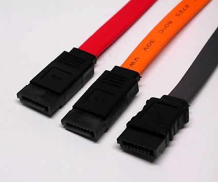
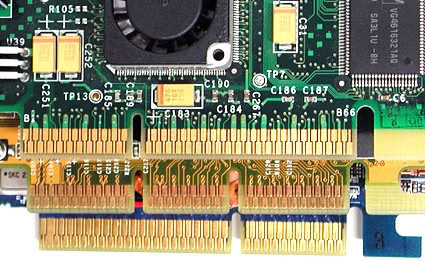
Serial ATA (SATA)
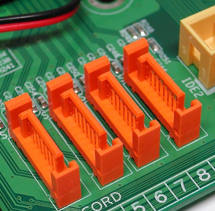
Four SATA connectors on a motherboard
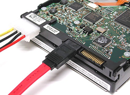
SATA is the serial bus for mass storage devices, mostly hard disks, and designed to replace the older parallel ATA interface. First generation Serial ATA is already in widespread use, with a maximum net data transfer rate of 150 MBps. The cable may be up to a maximum of 3.3 feet (1 m) in length. Point-to-point connections are typical for SATA, with one end of the SATA cable attaching to the PC's motherboard and the other directly to the hard drive. No additional devices can share that same cable, as is possible with Parallel ATA (where each cable supports one or two drives). The advantage here is that the older configuration of pairs of hard disks as master and slave drives is no longer necessary.
Recommended: Many SATA cables are delivered with protective end caps, to prevent damage to the delicate contacts
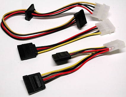
SATA power adapter in various formats
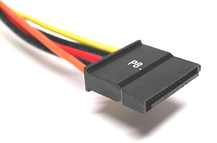
Power delivery for SATA hard disks
Cables come in various colors
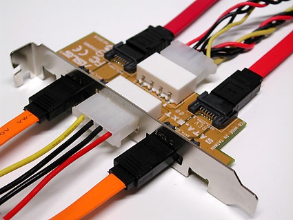
Although SATA was designed primarily for use inside a PC's case, there are products that make external SATA connections available, too.
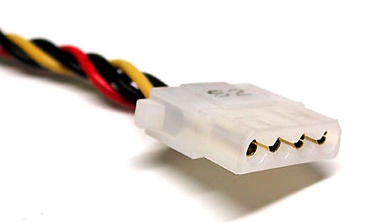
Power may be delivered to SATA drives in either of two ways:
1. with a classical Molex power connector as in this picture...
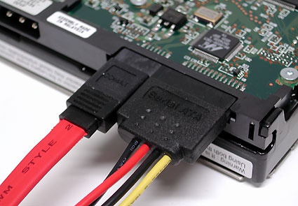
...or with a special SATA power cable as shown in this picture.
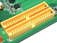
ATA/133 (Parallel ATA, UltraDMA/133 Or E-IDE)
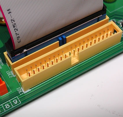
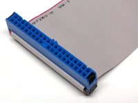
This is the parallel bus for data transfer from hard disks and optical drives (CD and DVD) also known as Parallel ATA, to contrast with Serial ATA. The latest version features an 40 pin, 80 wire Ribbon Cable to connect motherboards to drives. Each such cable can support up to a maximum of two devices, with one drive on a cable configured as the master drive, and the other as the slave. This setting is normally handled by a small jumper block somewhere on the drive.
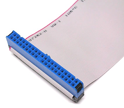
IDE Ribbon Cable
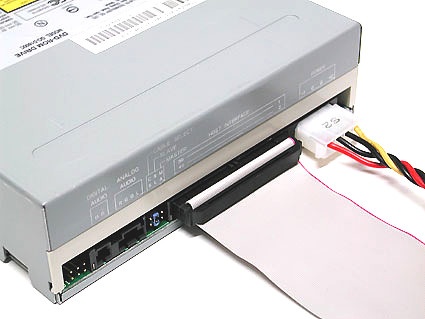
Connecting to a DVD drive: the red stripe on the Ribbon Cable should always be next to the power cable (to the right of the white peripheral connector in this photo)
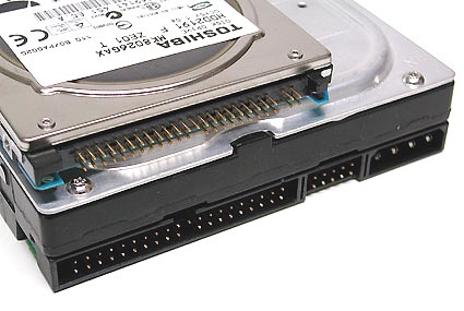
ATA/133 connector to a classical 3.5" hard disk (below) and a 2.5" model (above)
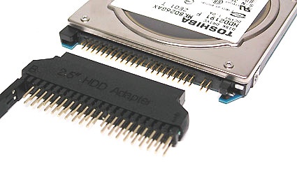
Those who want to install a 2.5" notebook hard disk in a typical desktop PC - if only for data synchronization - can use an adapter like this one.
Warning: In most cases, notches in the connector provide protection against reverse insertion or pin alignment/mismatch problems, but older cut-rate cables may lack these features. To prevent mishap, please obey the following rule: the side of the cable that's marked with a colored line (usually red) always attaches to the connector on the motherboard on the side that's labeled with the number 1, both for hard disks and CD/DVD drives (in fact, the stripe denotes the lead associated with pin 1 in the pin block). At the same time, the marked side of the Ribbon Cable should always be oriented toward the side of the drive where the power cables attach. Also, careful examination of the cable connectors and device or motherboard pin blocks show that both are missing a pin or a hole in the middle of one row. By matching up the missing pin on the drive or motherboard with the missing hole on the Ribbon Cable connector, correct alignment is always guaranteed.
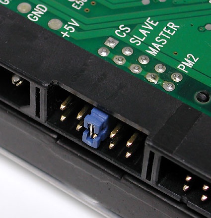
One Ribbon Cable can handle two devices, such as a combination of two hard disks or a hard disk and a DVD player or burner. When two devices share a Ribbon Cable, one must always be configured as the master, and the other as a slave. This configuration usually requires setting a jumper as shown in this picture. A single jumper usually handles this setting on most modern drives; if in doubt about placement, please consult the device documentation (or the vendor's website).
Glossary
- ATA = Advanced Technology Attachment
- E-IDE = Enhanced Integrated Drive Electronics
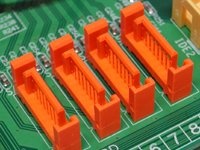
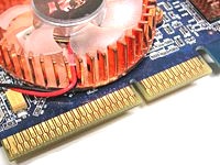
AGP - Accelerated Graphics Port
AGP-Slot with a retaining clip for the graphics card
Most of the graphics cards in PCs today use the Accelerated Graphics Port (AGP) as their standard interface. Fewer systems (mostly older ones) use PCI connected graphics cards instead. Coming on strong is PCI Express (PCIe) as the quick new kid on the graphics block. Warning: PCI Express is a serial bus, whereas PCI (without the Express suffix) is a parallel bus. PCI and PCI Express are completely different and shouldn't be switched!
An AGP graphics card (above) compared to a PCI Express graphics card (below)
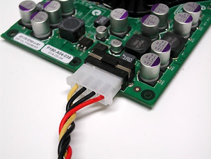
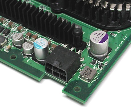
Workstation motherboards have an AGP Pro slot, which supplies additional power to energy-gobbling OpenGL graphics cards. It is designed to work with normal mainstream graphics cards as well. However, AGP Pro has not become widely accepted. Instead, power-hungry cards are equipped with a separate power source, either through a Molex or peripheral plug.
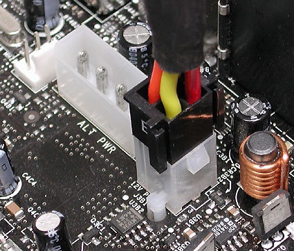
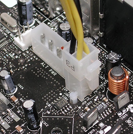
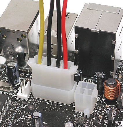
Supplementary power for a graphics card with a 4- or 6-pin peripheral power connector (typical on modern PSUs)
Supplementary power for a graphics card with a Molex connector
Within AGP there are four bandwidth classes:
| Standard |
Bandwidth |
| AGP 1X |
256 MB/s |
| AGP 2X |
533 MB/s |
| AGP 4X |
1066 MB/s |
| AGP 8X |
2133 MB/s |
Those who like to experiment with hardware should also be aware that there are two voltages for these interfaces as well. AGP 1X and 2X require 3.3 V, but AGP 4X and 8X require only 1.5 V; in addition, there's a Universal AGP card type that goes both ways. In any case, AGP slots all have built-in notches to prevent devices of the wrong type from being seated in incompatible slots.
Upper card with notch on the left for AGP 3.3 V. Middle: universal card with two notches (one for AGP 3.3 V, the other for AGP 1.5 V). Bottom card with notch on the right for AGP 1.5 V.
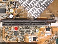
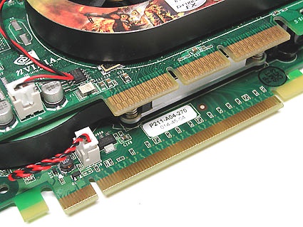
PCI Express: The Serial Bus
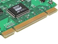
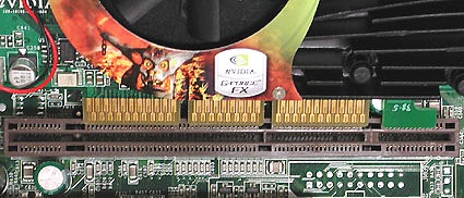
Motherboard expansions slots: PCI Express X16 lanes (above) and 2 PCI Express X1 lanes (below)
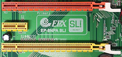
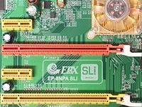
Dual PCI-Express slots for SLI graphics cards from NVIDIA; a small PCI Express x1 Lane slot has somehow blundered into the space between them.
As a serial bus, PCI Express should not be confused with PCI-X or plain vanilla PCI. These latter types use parallel signaling.
PCI Express (PCIe) is the latest interface for graphics cards; though in principle it is also usable for other peripheral components, at the present time there aren't any other mass market components that use this bus. On paper, PCIe X16 offers almost twice as much bandwidth per stream as does AGP 8X. But in practice, this advantage is not yet fully exploited in graphics cards available today.
AGP graphics card (above) compared to a PCI-Express graphics card (below)
From top to bottom: PCI Express x16 lanes (serial), two parallel PCI and PCI Express x1 lanes (serial)
| PCI Express Lanes |
Bandwidth per stream |
Bandwidth, duplex |
| 1 |
256 MB/s |
512 MB/s |
| 2 |
512 MB/s |
1 GB/s |
| 4 |
1 GB/s |
2 GB/s |
| 8 |
2 GB/s |
4 GB/s |
| 16 |
4 GB/s |
8 GB/s |
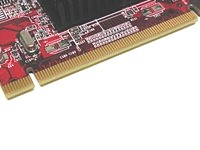
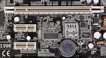
PCI And PCI-X: The Parallel Buses
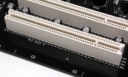
PCI is a bus standard for interfacing peripheral devices with a processor's chipset. Typical PCI products include network interface cards, modems, sound cards, and video editing boards.
On mainstream motherboards, PCI version 2.1 with 33 MHz bus clocking and 32 bit bud width is most typical. This offers bandwidth of up to 133 MBps. Vendors haven't widely adopted PCI 2.3 with 66 MHz bus clocking, so not too many compatible peripherals are available, though you will find some motherboards that support this standard.
Another development in the area of parallel PCI buses is known as PCI-X. These slots appear most frequently on workstation and server motherboards, where higher bandwidth for such devices as SCSI controllers or multi-port network interface cards is needed. As an example, PCI-X 1.0 offers bandwidth of up to 1 GBps at a bus clock of 133 MHz with 64 bit bus width.
The PCI 2.1 specification currently supports 3.3V for bus voltage. The left slot notch prevents insertion of older 5 V cards (like those show here in the picture)
Card with notch on the left, and PCI-slot with block to the left: everything fits correctly.
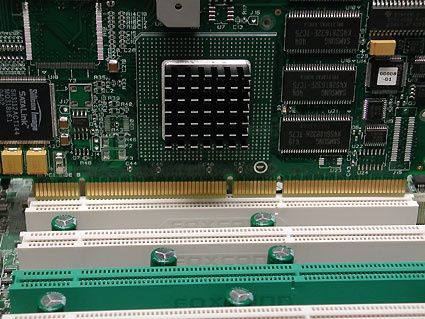
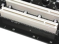
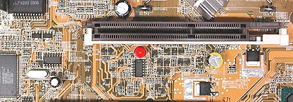
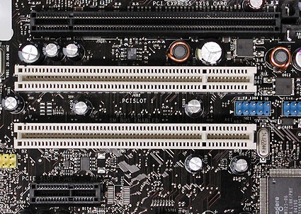
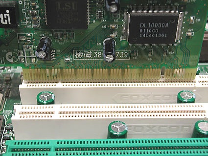
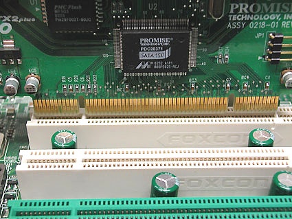
A RAID controller card in a 64-bit PCI-X slot
A classic 32-bit PCI slot above, with three 64-bit PCI-X slots below. The green slot offers ZCR (Zero Channel RAID) support.
Glossary
- PCI = Peripheral Component Interconnect
Power connectors And ATX Standards
The various types of power connections are shown in the following tables and illustrations.
Peripheral device connector
| AMD |
| Socket 462 |
| Power Supply Standard |
ATX12V 1.3 or higher |
| ATX plug |
20-pin |
| AUX plug (6-pin) |
not used |
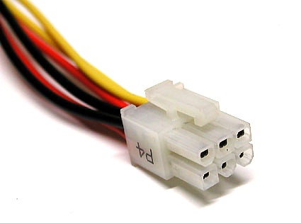
| P4 connector (4-pin 12V) |
rarely used |
| Socket 754 |
| Power Supply Standard |
ATX12V 1.3 or higher |
| ATX plug |
20-pin, sometimes 24-pin |
| AUX plug (6-pin) |
not used |
| P4 connector (4-pin 12V) |
sometimes needed |
| Socket 939 |
| Power Supply Standard |
ATX12V 1.3 or higher |
| ATX plug |
20-pin, sometimes 24-pin |
| AUX plug (6-pin) |
not used |
| P4 connector (4-pin 12V) |
sometimes needed |
| Intel |
| Socket 370 |
| Power Supply Standard |
ATX12V 1.3 or higher |
| ATX plug |
20-pin |
| AUX plug (6-pin) |
rarely used |
| P4 connector (4-pin 12V) |
rarely used |
| Socket 423 |
| Power Supply Standard |
ATX12V 1.3 or higher |
| ATX plug |
20-pin |
| AUX plug (6-pin) |
rarely used |
| P4 connector (4-pin 12V) |
needed |
| Socket 478 |
| Power Supply Standard |
ATX12V 1.3 or higher |
| ATX plug |
20-pin |
| AUX plug (6-pin) |
not used |
| P4 plug (4-pin 12V) |
needed |
| Socket 775 |
| Power Supply Standard |
ATX12V 2.01 or higher |
| ATX plug |
24-pin, sometimes 20-pin |
| AUX plug (6-pin) |
n/a |
| P4 plug (4-pin 12V) |
needed |
| P4 plug (8-pin 12V) |
945X chipset (DualCore) or higher often needs this connection |
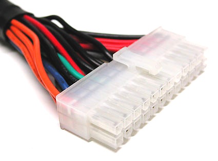
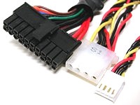
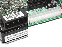
ATX plug with 24 pins (Extented ATX)
20-pin ATX motherboard connector
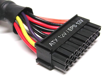
20-pin ATX cable
6-pin EPS connector
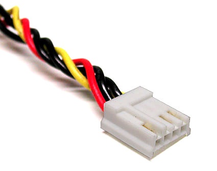
Has come and gone: power connection for a diskette drive
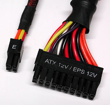
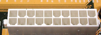
20/24 ping combination connector (ATX and EATX)
Don't do this! The 4-pin extender from a 20 to 24-pin combination connector may not be used in the 12V AUX port (it's usually too far away to reach anyway). This 4-pin extender either belongs in the Extended ATX port or will be unused on ATX 20-pin motherboards.
This is the way to go: the spearate 4-pin cable belongs in the 12V AUX port, easily recognizable by its color coding with 2 gold and 2 black wires.
Many motherboards require a peripheral power cable to be hooked up for supplementary power.
Welcome to contact us for cables & connectors.
Cell Phone: +86-158-8966-1771 Atten: Jacky
E-mail: jacky@micro-coaxial.com
Skype: jacky882010 MSN: jacky882010@hotmail.com
We provide a variety of cables assemblies and wire harnesses services for the leading electronics,
automotive,medical and special application product manufacturers. Our large range of customized
cable assemblies goes from the simple strand,coaxial transmission lines,Ribbon Cables to round cables,
USB and power supply cables as well as specially adapted cable sets for LCD displays,LCD inverter cables.
factory in China for manufacturing Signal Cord,Computer cables and Adapter to USB and Firewire cables,
LVDS cable,LCD cable,IDC Flat cables,Wire Harness
Common used connector part number:
I-PEX20453-020T,I-PEX20455-020E,I-PEX20453-030T,I-PEX20455-030E,
I-PEX20455-040E,I-PEX20453-040T,I-PEX20455-050E,I-PEX20453-050T,
I-PEX20524-030T,I-PEX20525-030E,I-PEX20524-040T,I-PEX20525-040E
I-PEX20472-030T,I-PEX20474-030E,I-PEX20472-040T,I-PEX20474-040E
I-PEX20346-030T,I-PEX20347-030E,I-PEX20345-040T,I-PEX20347-040E
I-PEX20373-020T,I-PEX20374-020E,I-PEX20373-030T,I-PEX20374-030E
I-PEX20373-040T,I-PEX20374-040E,I-PEX20373-050T,I-PEX20374-050E
I-PEX20438-040T,I-PEX20439-040E,I-PEX20438-050T,I-PEX20439-050E,
I-PEX20320-040T,I-PEX20320-050T,I-PEX20338-044T,I-PEX20384-040T
JAE FI-RE41CL,JAE FI-RE51CL,JAE FI-X30CL,JAE FI-X30C,JAE FI-NX40CL
JAE FI-J30C,JAE FI-JH30C,JAE FI-JT30C,JAE FI-VHP50C,JAE FI-D44C
JAE HD1S040HA1,TYCO 2023344-2,2023344-3,TYCO 5-2069716-3,
TYCO 5-2069716-2,Starconn 111A40-000RA-G3,Foxconn HF5508
HIROSE DF19-20S,KEL SL,KEL SSL,KEL USL,KEL XSL,KEL USLS
HONDA LVC-C20LPMSG+,HONDA LVC-D20LPMSG+,HONDA LVC-D20SFYG
HONDA LVC-C30LPMSG+,HONDA LVC-D30LPMSG+,HONDA LVC-D30SFYG
HONDA LVC-C40LPMSG+,HONDA LVC-D40LPMSG+,HONDA LVC-D40SFYG
HONDA LVX-A30LMSG+,HONDA LVX-A30SFYG+
HONDA LVX-A40LMSG+,HONDA LVX-A40SFYG+
ACES88441-040/ACES50203-040/ACES88341-040
ACES 91209-01011/ACES 91214/ACES 88107
|
|


 SGC cable,MCC cable,MCX cable,I-PEX cable,LVDS cable,eDP cable,Custom cable,Cable OEM,Cable Assembly,LCD cable,IPEX cable,20455-040E,20474-030E,20525-030E,ACES 88441,ACES 91209