intel System-Validation Methodology for Embedded DisplayPort kabel,eDP cable,custom cable
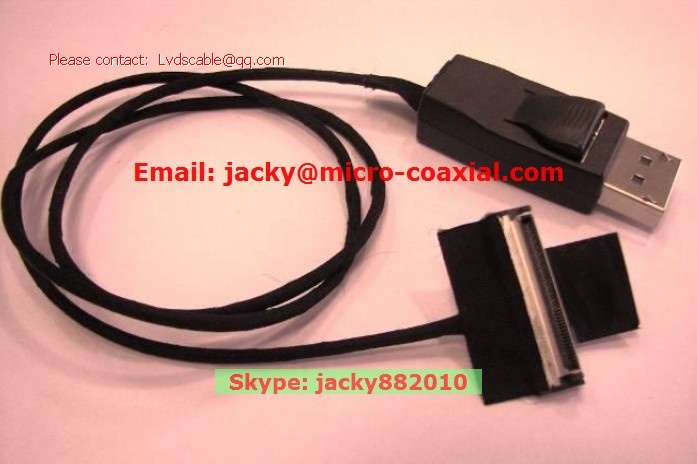
eDP*-to-DisplayPort* Cable
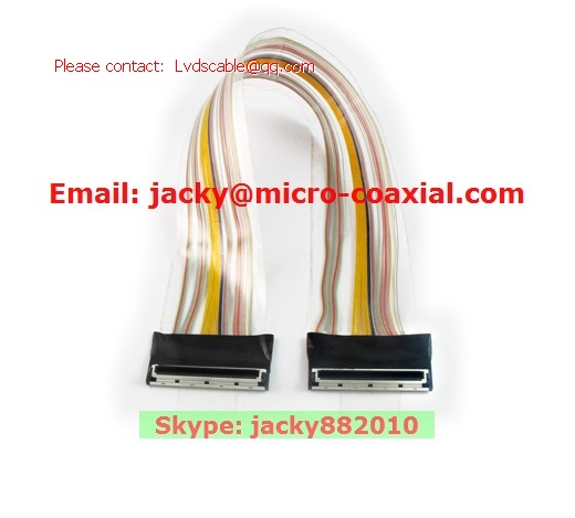
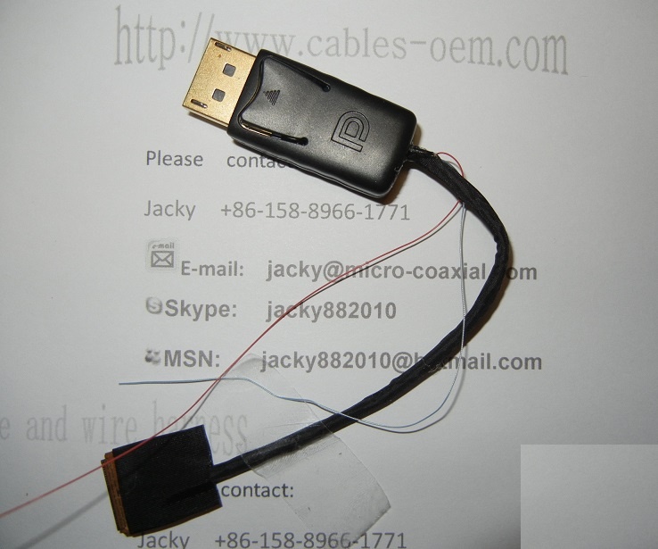
A specially designed eDP-to-DisplayPort cable is needed (see Figure 7)
because of the physical incompatibility of the eDP Tx and DisplayPort Rx
connectors. Since the eDP and DisplayPort standards are very similar, only a
passive cable is needed, no level shifting.
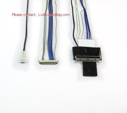
The DisplayPort connector has 20 pins, which include four differential lanes of
the main link, a differential auxiliary channel (AUX) for slow speed control,
Hot-Plug Detect signal (HPD), ground pins, CONFIG control pins, and two
power pins. The eDP connector has those and additional optional pins, like
brightness control, backlight and ambient light sensing. The eDP standard
allows various
connectors with 44/40/30/20 pins. However, this paper
demonstrates only the 44-pin connector, since the others follow similar
principles. Another reason for showing the 44-pin connector is that it used on
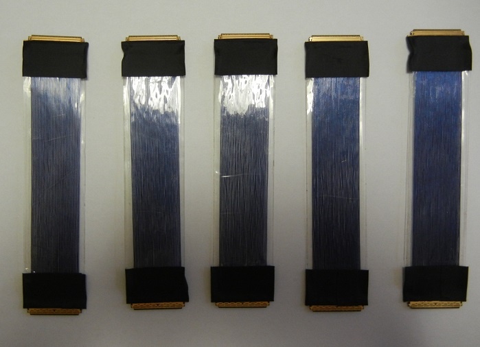
The typical cable’s part number is LA10EM006-2N. Its length is 22’’ (559
mm). The cable length has to match 4 db insertion loss at 1.35 GHz. The
frequency of 1.35 GHz is the first harmonic of the 2.7 Gb/sec DisplayPort
data signal. The data lanes’ wires are twin-ax coaxial cables.
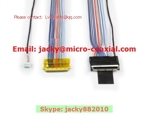
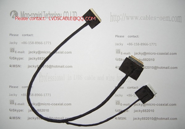
Several other cables, which customers may put in their systems, can be
tested:
Different cable lengths - 16’’ and 28’’, not only 22’’;
A cable with coaxial wires (not twin-ax) for the main lanes;
Please contact:
Cell Phone: +86-158-8966-1771 Atten: Jacky
E-mail: jacky@micro-coaxial.com / lvdscable@qq.com
Skype: jacky882010


 SGC cable,MCC cable,MCX cable,I-PEX cable,LVDS cable,eDP cable,Custom cable,Cable OEM,Cable Assembly,LCD cable,IPEX cable,20455-040E,20474-030E,20525-030E,ACES 88441,ACES 91209