An electrical connector is an electro-mechanical device for joining electrical circuits as an interfaceusing a mechanical assembly. The connection may be temporary, as for portable equipment, require a tool for assembly and removal, or serve as a permanent electrical joint between two wires or devices. [1]
There are hundreds of types of electrical connectors. connectors may join two lengths of flexible copperwire or cable, or connect a wire or cable or optical interface to an electrical terminal.
In computing, an electrical connector can also be known as a physical interface (compare Physical Layer inOSI model of networking). Cable glands, known as cable connectors in the U.S., connect wires to devices mechanically rather than electrically and are distinct from quick-disconnects performing the latter.
[edit]connectors">Properties of electrical connectors
Electrical connectors are characterised by their pinout and physical construction, size, contact resistance, insulation between pins, ruggedness and resistance to vibration, resistance to entry of water or other contaminants, resistance to pressure, reliability, lifetime (number of connect/disconnect operations before failure), and ease of connecting and disconnecting.
They may be keyed to prevent insertion in the wrong orientation, connecting the wrong pins to each other, and have locking mechanisms to ensure that they are fully inserted and cannot work loose or fall out. Some connectors are designed such that certain pins make contact before others when inserted, and break first on disconnection; this protects circuits typically in connectors that apply power, e.g. connecting safety ground first, and sequencing connections properly in hot swapping applications.
It is usually desirable for a connector to be easy to identify visually, rapid to assemble, require only simple tooling, and be inexpensive. In some cases an equipment manufacturer might choose a connector specifically because it is not compatible with those from other sources, allowing control of what may be connected. No single connector has all the ideal properties; the proliferation of types is a reflection of differing requirements.
Many connectors are keyed, with some mechanical component which prevents mating except with a correctly-oriented matching connector. This can be used to prevent incorrect or damaging interconnections, either preventing pins from being damaged by being jammed in at the wrong angle or fitting into imperfectly fitting plugs, or to prevent damaging connections, such as plugging an audio cable into a power outlet. For instance, XLR connectors have a notch to ensure proper orientation, while Mini-DIN plugs have a plastic projection, which fits into a corresponding hole in the socket and prevent different connectors from being pushed together (they also have a notched metal skirt to provide secondary keying).
[edit]Locking mechanisms
Some connector housings are designed with locking mechanisms to prevent inadvertent disconnection or poor environmental sealing. Locking mechanism designs include locking levers of various sorts, screw locking, and toggle or bayonet locking. Depending on application requirements, housings with locking mechanisms may be tested under various environmental simulations that include physical shock and vibration, water spray, dust, etc. to ensure the integrity of the electrical connection and housing seals.
[edit]connectors">Types of electrical connectors
A terminal is a simple type of electrical connector that connects two or more wires to a single connection point. Wire nuts are another type of single point connector.
[edit]Terminal blocks

Terminal blocks of various types.
Terminal blocks (also called terminal boards or strips) provide a convenient means of connecting individual electrical wires without a splice or physically joining the ends. They are usually used to connect wiring among various items of equipment within an enclosure or to make connections among individually enclosed items. Since terminal blocks are readily available for a wide range of wire sizes and terminal quantity, they are one of the most flexible types of electrical connector available. Some disadvantages are that connecting wires is more difficult than simply plugging in a cable and the terminals are generally not very well protected from contact with persons or foreign conducting materials.
One type of terminal block accepts wires that are prepared only by removing (stripping) a short length of insulation from the end. Another type accepts wires that have ring or spade terminal lugs crimped onto the wires. Printed circuit board(PCB) mounted terminal blocks allow individual wires to be connected to the circuit board. PCB mounted terminal blocks are soldered to the board, but they are available in a pull-apart version that allows the wire-connecting half of the block to be unplugged from the part that is soldered to the PCB.
Main article:
Binding postA general type of connector that simply screws or clamps bare wire to a post; such connectors are frequently used in electronic test equipment and audio. Many, but not all binding posts will also accept a banana connector plug.
A type of solderless connection.
[edit]connectors">Insulation displacement connectors
Since stripping the insulation from wires is time-consuming, many connectors intended for rapid assembly use insulation-displacement connectors so that insulation need not be removed from the wire. These generally take the form of a fork-shaped opening in the terminal, into which the insulated wire is pressed and which cut through the insulation to contact the conductor within. To make these connections reliably on a production line, special tools are used which accurately control the forces applied during assembly. If properly assembled, the resulting terminations are gas-tight and will last the life of the product. A common example is the multi-conductor flat Ribbon cable used in computer disk drives; to terminate each of the many (approximately 40) wires individually would be slow and error-prone, but an insulation displacement connector can terminate all the wires in (literally) one stroke. Another very common use is so-called punch down blocks used for terminating telephone wiring.
Insulation displacement connectors are usually used with small conductors for signal purposes and at low voltage. Power conductors carrying more than a few amperes are more reliably terminated with other means, though "hot tap" press-on connectors find some use in automotive applications for additions to existing wiring.
[edit]connectors">Plug and socket connectors
Plug and socket connectors are usually made up of a male plug (typically pin contacts) and a female receptacle (typically socket contacts), althoughhermaphroditic connectors exist, such as the original IBM token ring LAN connector. Plugs generally have one or more pins or prongs that are inserted into openings in the mating socket. The connection between the mating metal parts must be sufficiently tight to make a good electrical connection and complete the circuit. When working with multi-pin connectors, it is helpful to have a pinout diagram to identify the wire or circuit node connected to each pin.
| Plug and Socket connectors |
|
|
Detail of mating surfaces of hermaphrodite connector. |
|
Jack commonly refers to a connector often with the female electrical contact or socket, and is the "more fixed" connector of a connector pair. Plugcommonly refers to a movable connector, often (but not always) with the male electrical contact or pin, and is the movable (less fixed) connector of a connector pair.
Some connector styles[2] may contain both pin and socket connection types.
A jack is properly described as a connector that is designed to be fixed on the surface of a bulkhead or enclosure; "The stationary (more fixed) connector of a mating pair shall be designated J or X"[3] where J means jack.[4] Its counterpart, the "plug," is designed to attach to a wire, cable or removable electrical assembly; "The movable (less fixed) connector of a mating pair shall be designated P" [5] where P means plug. This convention is currently defined in ASME Y14.44-2008 which is the current actively maintained follow on to the withdrawn IEEE 200-1975; IEEE 200-1975 was derived from the long withdrawn MIL-STD-16 which dates back at least to the 1950s which highlights the heritage of this connector naming convention. IEEE 315-1975 works alongside ASME Y14.44-2008 to define J, P and X references.
A plug is properly described as a connector that is designed to be attached to a wire, cable or removable electrical assembly: "The movable (less fixed) connector of a mating pair shall be designated P"[6] where P means plug[7].
The term jack occurs in several related terms:
- The RCA jack, also known as a "phono jack", common to consumer electronics.
- The EIAJ jack designed for consumer appliances requiring less than an 18.0 volt power supply.
When the description includes a diameter, the term refers to the jack that matches the corresponding diameter of plug. For example:
- 6.35 mm or 1/4" jack
- 3.5 mm (1/8") miniature jack
- 2.5 mm (3/32") subminiature
A headphone (or earphone) jack is commonly one of the three standard sizes of 3-conductor TRS jacks, but the term could refer to any socket used for this purpose.
[edit]connectors">Component and device connectors

High-power transistor switch module with large screw
connectors and small crimped-on "Fast-on"
connectors
Electrical and electronic components and devices sometimes have plug and socket connectors or terminal blocks, but individual screw terminals and fast-on or quick-disconnect terminals are more common. Small components have bare lead wires for soldering. They are manufactured using casting.
[edit]Blade connector
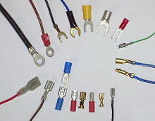
Blade
connectors (lower half of photo). Ring and spade terminals (upper half).
A blade connector is a type of single wire connection using a flat conductive blade which is inserted into a blade receptacle. Usually both blade connector and blade receptacle have wires attached to them either through soldering of the wire to the blade or crimping of the blade to the wire. In some cases the blade is an integral manufactured part of a component (such as a switch or a speaker unit), and a blade receptacle is pushed onto the blade to form a connection.
A common type of blade connector is the "Faston". While Faston is a trademark of TE Connectivity (formerly Tyco Electronics), it has come into common usage. Faston connectors come in male and female types. They have been commonly used since the 1970s.
[edit]Ring and spade terminals

Ring style wire end blade
connectors are normally sold in lots.
The connectors in the top row of the image are known as ring terminals and spade terminals (sometimes called split ring terminals). Electrical contact is made by passing a screw or bolt through them. The spade terminal form factor facilitates connections since the screw or bolt can be left partially screwed in as the spade terminal is removed or attached. Their sizes can be determined by the size of the conducting wire AWG and thescrew/bolt diameter size designation.
[edit]8P8C connector

8P8C Connector crimped to cable
8P8C is short for "eight positions, eight conductors", and so an 8P8C modular connector (plug or jack) is amodular connector with eight positions, all containing conductors. The connector is probably most famous for its use in Ethernet and widely used on CAT5 cables.
The 8P8C modular plugs and jacks look very similar to the plugs and jacks used for FCC's registered jack RJ45 variants, although the specified RJ45 socket is not compatible with 8P8C modular plug connectors. It neither uses all eight conductors (but only two of them for wires plus two for connecting a programming resistor) nor does it fit into 8P8C because the true RJ45 is "keyed".
[edit]connectors">D-subminiature connectors
Main article:
D-subminiatureThe D-subminiature electrical connector is commonly used for the RS-232 serial port on modems and IBM compatiblecomputers. The D-subminiature connector is used in many different applications, for computers, telecommunications, and test and measurement instruments. A few examples are monitors (MGA, CGA, EGA), theCommodore 64, MSX, Apple II, Amiga, and Atari joysticks and mice, and game consoles such as Atari and Sega.
The Universal Serial Bus is a serial bus standard to interface devices, founded in 1996. It is currently widely used among PCs, Apple Macintosh and many other devices. There are several types of USB connectors, and some have been added as the specification has progressed. The most commonly used is the (male) series "A" plug onperipherals, when the cable is fixed to the peripheral. If there is no cable fixed to the peripheral, the peripheral always needs to have a USB "B" socket. In this case a USB "A" plug to a USB "B" plug cable would be needed. USB "A" sockets are always used on the host PC and the USB "B" sockets on the peripherals. It is a 4-pin connector, surrounded by a shield. There are several other connectors in use, the mini-A, mini- B and mini-AB plug and socket (added in the On-The-Go Supplement to the USB 2.0 Specification).

A panel-mounted
IEC 60320 C14male connector designed to accept AC line power
Power connectors must protect people from accidental contact with energized conductors. Power connectors often include a safety ground connection as well as the power conductors. In larger sizes, these connectors must also safely contain any arc produced when an energized circuit is disconnected or may require interlocking to prevent opening a live circuit.
[edit]connectors">Radio frequency connectors
Main article:
RF connector

A male 50 ohm BNC connector
connectors used at radio frequencies must not change the impedance of the transmission line of which they are part, otherwise Signal reflection and losses will result. A radio-frequency connector must not allow external signals into the circuit, and must prevent leakage of energy out of the circuit. At lower radio frequencies simple connectors can be used with success, but as the radio frequency increases, transmission line effects become more important, with small impedance variations from connectors causing the signal to reflect from the connector, rather than to pass through. At UHF and above, silver-plating of connectors is common to reduce losses.
For Wi-Fi antennas the R-TNC connectors are used. A BNC connector is common for radio and test equipment used up to about 1 GHz.
Main article:
DC connectorA DC connector is an electrical connector for supplying direct current (DC) power. For portable consumer electronic devices, the Coaxial power connector is frequently used, but many other types of connectors also exist.
Hybrid connectors have housings with inserts that allow the intermixing of many connector types, such as those mentioned above. These housings may also allow intermixing of electrical and non-electrical interfaces, examples of the latter being pneumatic line connectors, and optical fiber connectors. Because hybrid connectors are modular in nature, they tend to simplify assembly, repair, and future modifications. They also allow the creation of composite cable assemblies that can reduce equipment installation time by reducing the number of individual cable and connector assemblies.
[edit]Electrical cables
[edit]Termination and gender
When used to terminate cables, in some applications both ends of the cable are terminated using identical connectors (generally male), as inregistered jack telephone cables or Ethernet over twisted pair network cables, while in other applications the two ends are terminated differently, either with male and female of the same connector (as in an extension cord), which ends can be connected to each other in a loop, or with incompatible connectors, in an adapter cable.
[edit]Wiring and pinouts
For more details on this topic, see
pinout.
When a cable is terminated by a connector, the various wires in the cable are connected to contacts (pins) in the connector. The most common methods of connecting pins to individual wires are soldering, insulation displacement, insulation piercing, screw clamping, axial screw termination, cage clamping, crimping, press-in termination, andwire wrapping. Some of these wiring methods can be accomplished without specialized tools. Other methods, while requiring a special tool, can assemble connectors to a cable much faster and more reliably, and make repairs easier.
If one has specified wires within a cable (for instance, the colored Ethernet cable wires in TIA/EIA-568-B), then the order in which different color wires are attached to different connector pins defines the wiring scheme. Different ways of wiring numbered connector pins at the two ends of a cable creates different assemblies, which may appear identical but behave differently.
If both ends of a cable have the same connector, or male and female versions of a connector, or even similar connectors (such as RJ11 and BS 6312, both of which often have 6P4C (6 positions and 4 contacts)), there is a notion of straight through cable and crossover cable:
- in a straight through cable, pins on one end correspond exactly to the corresponding pins on the other end (pin 1 to pin 1, pin 2 to pin 2, etc.).
- Using the same wiring (a given color wire connects to a given number pin, the same at both ends) at each end yields a straight through cable.
- in a crossover cable, pins do not so correspond; most often in crossover cables some cables are swapped, meaning that if pin 1 on one end goes to pin 2 on the other end, then pin 2 on the first end goes to pin 1 on the second end, and not to pin 3 or some other: such crossover cables are symmetric, meaning that they work identically regardless of which way you plug them in (if you turn the cable around, it still connects the same pins as before).
- Using different wiring (a given color wire connects to one number pin at one end, and a different number pin at the other) at each end yields a crossover cable.
A well-known crossover cable is the Ethernet crossover cable, which converts between T568A and T568B termination.
What matters specifically is not "which contact corresponds to which wire", but rather "which contact on one connector corresponds to which contact on the other connector": to illustrate the distinction, T568A straight through cables and T568B straight through cables are electrically identical: pin 1 on one end corresponds to pin 1 on the other end, though in the T568A it is a green/white striped wire that connects them, while in T568B it is an orange/white striped wire that connects them. However, a cable wired with T568A at one end and T568B at the other is a crossover cable.
The name "straight through" is suggestive but slightly misleading: if one has a ribbon cable, such that all wires are in fact straight and in a line, the pinouts at the two ends are the mirror of each other: the left-most wire on one end is the right-most wire on the other.
[edit]See also
[edit]References
- ^ Robert S. Mroczkowski, Electrical Connector Handbook Theory and Applications, McGraw Hill, 1998 ISBN 0-07-0414101-7, chapter 1
- ^ The Art of Electronics, 2nd Edition, p56. Cambridge University Press. 1989.
- ^ Reference Designations for Electrical and Electronics Parts and Equipment: ASME Y14.44-2008 : Section 2.1.5.3 (2). ASME, Fairfield, NJ. 2008.
- ^ Graphic Symbols for Electrical and Electronics Diagrams (Including Reference Designation Letters): IEEE-315-1975 (Reaffirmed 1993): Section 22. IEEE and ANSI, New York, NY. 1993.
- ^ Reference Designations for Electrical and Electronics Parts and Equipment: ASME Y14.44-2008 : Section 2.1.5.3 (1). ASME, Fairfield, NJ. 2008.
- ^ Reference Designations for Electrical and Electronics Parts and Equipment: ASME Y14.44-2008 : Section 2.1.5.3 (1). ASME, Fairfield, NJ. 2008.
- ^ Graphic Symbols for Electrical and Electronics Diagrams (Including Reference Designation Letters): IEEE-315-1975 (Reaffirmed 1993): Section 22. IEEE and ANSI, New York, NY. 1993.
- Foreman, Chris, "Sound System Design", Handbook for Sound Engineers, Third Edition, Glen M. Ballou, Ed., Elsevier Inc., 2002, pp. 1171–2.
[edit]External links
 Media related to Electrical connectors at Wikimedia Commons


 SGC cable,MCC cable,MCX cable,I-PEX cable,LVDS cable,eDP cable,Custom cable,Cable OEM,Cable Assembly,LCD cable,IPEX cable,20455-040E,20474-030E,20525-030E,ACES 88441,ACES 91209